
HERBLITZ
Standard feeder
Technical data (Type A-B-C)
| Type | Max. strip width [mm] | Stroke [mm] | Strip tickness [mm] | Cycles min. | Pressure of fixed clamp [kg] | Pressure of mobile clamp [kg] | Traction force [kg] | Air consuption [liters/min.] | Weight [kg] |
| A050T | 50 | 50 | 1.30 | 280 | 64 | 120 | 24 | 50 | 3.9 |
| A100T | 50 | 100 | 1.30 | 200 | 64 | 120 | 24 | 71 | 4.8 |
| A150T | 50 | 150 | 1.20 | 160 | 64 | 120 | 24 | 80 | 5.7 |
| A200T | 50 | 200 | 1.10 | 130 | 64 | 120 | 24 | 85 | 6.1 |
| A250T | 50 | 250 | 1.00 | 110 | 64 | 120 | 24 | 90 | 7.3 |
| B050T | 75 | 50 | 1.30 | 260 | 64 | 120 | 24 | 46 | 4.8 |
| B100T | 75 | 100 | 1.30 | 190 | 64 | 120 | 24 | 67 | 5.8 |
| B150T | 75 | 150 | 1.20 | 150 | 64 | 120 | 24 | 78 | 6.8 |
| B200T | 75 | 200 | 1.10 | 110 | 64 | 120 | 24 | 77 | 7.8 |
| B250T | 75 | 250 | 1.00 | 90 | 64 | 120 | 24 | 78 | 8.8 |
| C050T | 100 | 50 | 1.30 | 210 | 64 | 120 | 24 | 37 | 5.6 |
| C100T | 100 | 100 | 1.30 | 160 | 64 | 120 | 24 | 56 | 6.6 |
| C150T | 100 | 150 | 1.20 | 120 | 64 | 120 | 24 | 68 | 7.8 |
| C200T | 100 | 200 | 1.10 | 90 | 64 | 120 | 24 | 63 | 9.0 |
| C250T | 100 | 250 | 1.00 | 80 | 64 | 120 | 24 | 70 | 1 |
Medium feeder
Technical Data (Type BX-CX-DX)
| Type | Max. strip width [mm] | Stroke [mm] | Strip tickness [mm] | Cycles min. | Pressure of fixed clamp [kg] | Pressure of mobile clamp [kg] | Traction force [kg] | Air consuption [liters/min.] | Weight [kg] |
| BX050 | 75 | 50 | 2.00 | 260 | 70 | 158 | 41 | 64 | 6.2 |
| BX100 | 75 | 100 | 2.00 | 180 | 70 | 158 | 41 | 92 | 7.7 |
| BX150 | 75 | 150 | 1.80 | 150 | 70 | 158 | 41 | 115 | 9.2 |
| BX200 | 75 | 200 | 1.60 | 120 | 70 | 158 | 41 | 122 | 10.7 |
| BX250 | 75 | 250 | 1.50 | 90 | 70 | 158 | 41 | 115 | 12.2 |
| CX050 | 100 | 50 | 2.00 | 240 | 70 | 158 | 41 | 61 | 7.3 |
| CX100 | 100 | 100 | 1.80 | 170 | 70 | 158 | 41 | 87 | 8.8 |
| CX150 | 100 | 150 | 1.70 | 140 | 70 | 158 | 41 | 107 | 10.2 |
| CX200 | 100 | 200 | 1.60 | 110 | 70 | 158 | 41 | 112 | 11.7 |
| CX250 | 100 | 250 | 1.50 | 90 | 70 | 158 | 41 | 115 | 13.1 |
| DX050 | 150 | 50 | 1.60 | 230 | 70 | 158 | 41 | 59 | 9.6 |
| DX100 | 150 | 100 | 1.40 | 160 | 70 | 158 | 41 | 82 | 11.2 |
| DX150 | 150 | 150 | 1.20 | 130 | 70 | 158 | 41 | 100 | 12.7 |
| DX200 | 150 | 200 | 1.00 | 100 | 70 | 158 | 41 | 102 | 14.2 |
| DX250 | 150 | 250 | 1.00 | 80 | 70 | 158 | 41 | 103 | 15.7 |
Heavy feeder

Technical data (Type P-S-Z)
| Type | Max. strip width [mm] | Stroke [mm] | Strip tickness [mm] | Cycle min. | Pression of fixed clamp [kg] | Pression of mobile clamp [kg] | Traction force [kg] | Air consuption [liters/min.] | Weight [kg] |
| P1 | 155 | 100 | 3.8 | 140 | 280 | 604 | 108 | 184 | 32 |
| P2 | 155 | 200 | 3.5 | 120 | 280 | 604 | 108 | 314 | 39 |
| P3 | 155 | 300 | 3.0 | 70 | 280 | 604 | 108 | 275 | 46 |
| S1 | 205 | 100 | 3.0 | 130 | 280 | 604 | 108 | 170 | 38 |
| S2 | 205 | 200 | 3.0 | 110 | 280 | 604 | 108 | 288 | 45 |
| S3 | 205 | 300 | 3.0 | 70 | 280 | 604 | 108 | 275 | 54 |
| Z1 | 305 | 100 | 3.0 | 120 | 280 | 604 | 108 | 158 | 48 |
| Z2 | 305 | 200 | 3.0 | 95 | 280 | 604 | 108 | 249 | 58 |
| Z3 | 305 | 300 | 2.5 | 60 | 280 | 604 | 108 | 235 | 69 |
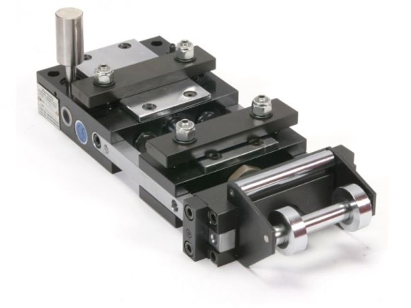
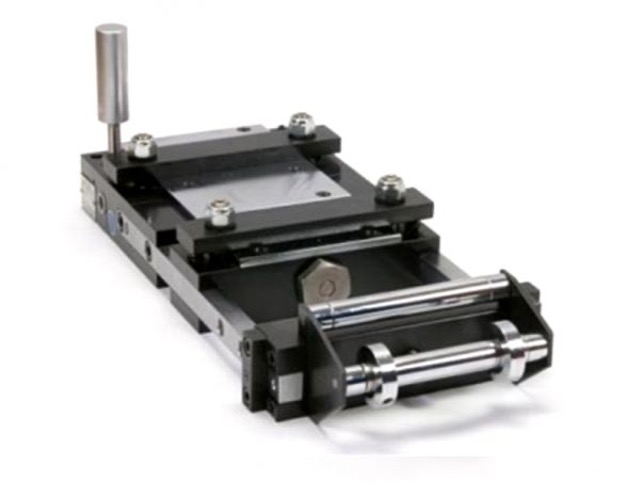
Feeder for tråd type A
The model type A is suggsted for max wire diameter 1 mm and were it is not neccessary to adopt a indle straightener.
It is possible to predispose a guide device by a telescopic tube to avoid any permanent wave.
| Type | Max. wire diameter [mm] | Max. stroke[mm] | Cycles min. | Pressure of fix clamps [kg] | Pressure of mobile clamps [kg] | Traction force [kg] | Air consumption [liters/min.] | Weight [kg] |
| A050T | 1 | 50 | 250 | 64 | 120 | 24 | 50 | 3.9 |
| A100T | 1 | 100 | 1250 | 64 | 120 | 24 | 71 | 4.8 |
| A150T | 1 | 150 | 160 | 64 | 120 | 24 | 80 | 5.7 |
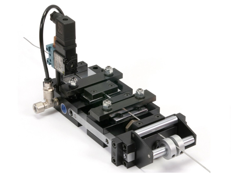
Feeder for tråd type BX
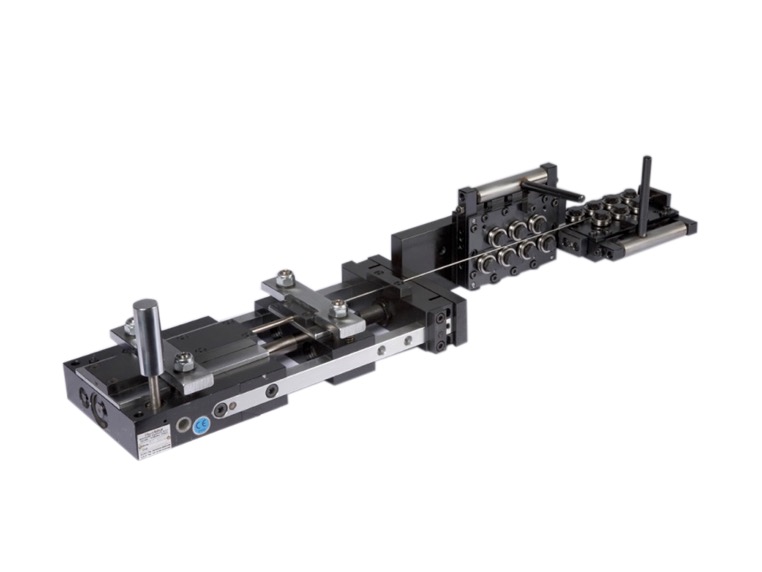
The model type BX is suggested for a wire with max diameter 3 mm and when is neccessary to predispose an indle straightener.
If the wire goes trought the straightening rolls, the value of the max. diameter can be reduced depending of the elastic coefficient of the wire to be feed.
In case of flexible or very narrow wires, it is possbile to apply the guiding device by telescopic tube to avoid any permanent wave.
| Type | Max. stroke [mm] | Max. wire diameter [mm] | Cycles min. | Pressure of fix clamps [kg] | Pressure of mobile clamps [kg] | Traction force [kg] | Air consumptiom [litri/min.] | Weight [kg] |
| BX050 | 50 | 3 | 260 | 70 | 158 | 41 | 64 | 6.2 |
| BX100 | 100 | 3 | 180 | 70 | 158 | 41 | 92 | 7.7 |
| BX150 | 150 | 3 | 150 | 70 | 158 | 41 | 115 | 9.2 |
| BX200 | 200 | 3 | 120 | 70 | 158 | 41 | 122 | 10.7 |
| BX250 | 250 | 3 | 90 | 70 | 158 | 41 | 115 | 12.2 |
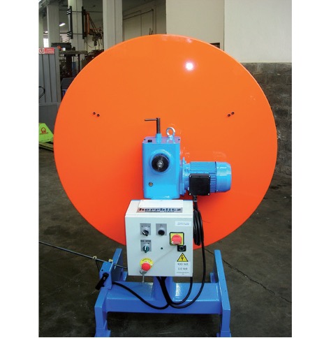
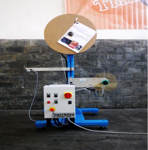
Enkel coiling/ASPO SERIE N0 E 0
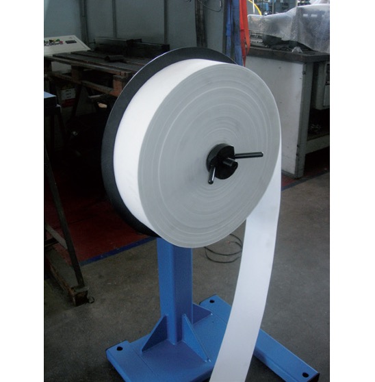
TECHNICAL FEATURES
SPINDLE EXPANSION
Models NO 1/20 and NO 2/50 C are used for decoiling strips wound onto reels: these may be in plastic or in other material, with or without lateral disks for containment. Reels usually have a fix internal diameter, depending on the supplier: the spindle of our decoiler must be thus manufactured according to that diameter in order to enable the loading of the coil, that will then be locked in position onto the shaft by means of a conical screw clamp.
Models NO2/200 and NO3/300 are equipped with motorised expansion, actuated directly from the control panel.
SPEED
Fix at 14 rotations / minute on standard versions
On demand variable speed (servo-ventilated motor + inverter)
LOOP CONTROL
Sensor on the ground for standard models
On request feeler arm or bascule roller
On demand ultrasound
(if the decoiler is equipped with variable speed, the speed adjusts automatically on the basis of the height of the loop from the ground) The same models are available without motor and with disk brake with manual adjustment done by a handle.
Type elektrisk A/coiling
Type elektrisk B/coiling
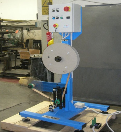
Type elektrisk C/ coiling
RAPIDAIR FEEDERE/COILING
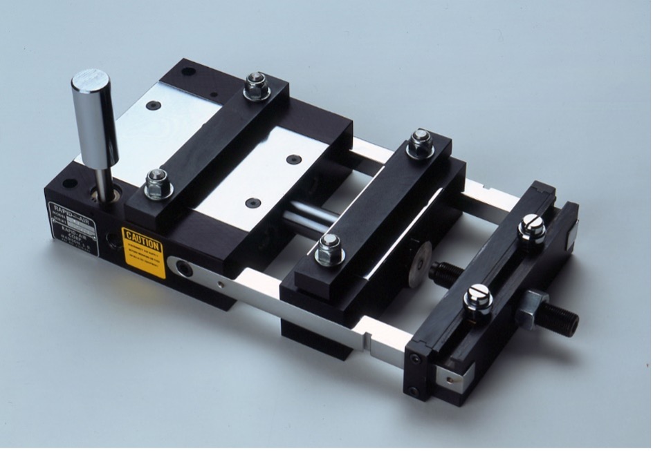
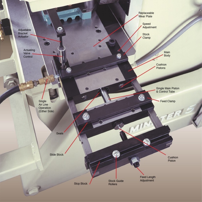
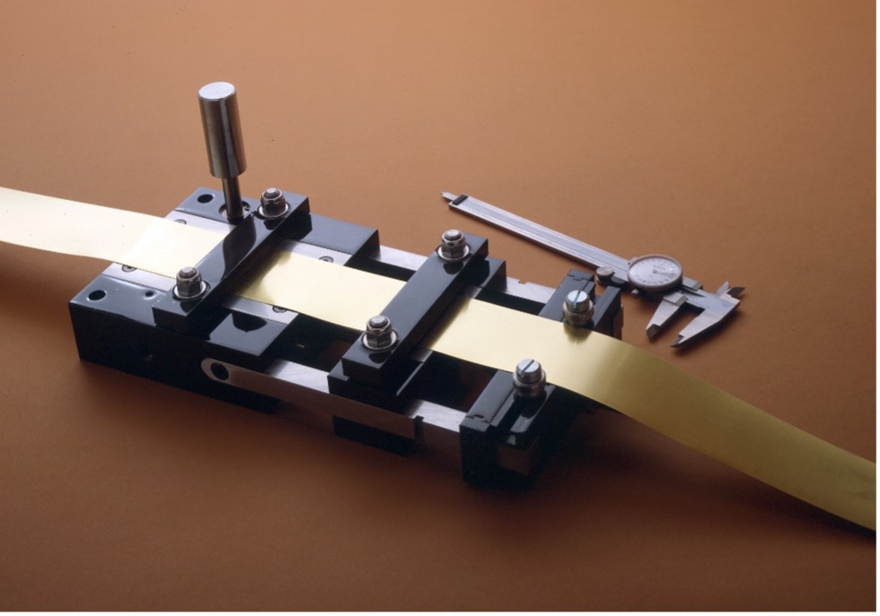
Air Feed Models
| Model | Max Material Width | Max Stock Length*1 | Stock Thickness*2 | Speed Cycle/Min. (recom.)*3 | Pulling Capacity*4 |
| A2 | 1 – 1/2” (38.1mm) | 2” (50mm) | .002” – .040” (.051-1.02mm) | 260 | 20 lbs (9.1kg) |
| A4 | 1 – 1/2” (38.1mm) | 4” (101mm) | .002” – .040” (.051-1.02mm) | 200 | 20 lbs (9.1kg) |
| A6 | 1 – 1/2” (38.1mm) | 6” (152mm) | .002” – .040” (.051-1.02mm) | 160 | 20 lbs (9.1kg) |
| B2 | 2 – 1/2” (63.5mm) | 2” (50mm) | .002” – .040” (.051-1.02mm) | 230 | 20 lbs (9.1kg) |
| B4 | 2 – 1/2” (63.5mm) | 4” (101mm) | .002” – .035” (.051-0.89mm) | 175 | 20 lbs (9.1kg) |
| C3 | 3” (76.2mm) | 3” (76mm) | .003” – .075” (.076-1.91mm) | 195 | 45 lbs (20.5kg) |
| C6 | 3” (76.2mm) | 6” (152mm) | .003” – .062” (.076-1.57mm) | 140 | 45 lbs (20.5kg) |
| C12 | 3” (76.2mm) | 12” (305mm) | .003” – .062” (.076-1.57mm) | 85 | 45 lbs (20.5kg) |
| D3 | 4” (101.6mm) | 3” (76mm) | .003” – .075” (.076-1.91mm) | 175 | 45 lbs (20.5kg) |
| D6 | 4” (101.6mm) | 6” (152mm) | .003” – .062” (.076-1.57mm) | 135 | 45 lbs (20.5kg) |
| W6 | 2” (50.8mm) | 6” (152mm) | .003” – .090” (.076-2.29mm) | 140 | 100 lbs (45.5kg) |
| W12 | 2” (50.8mm) | 12” (305mm) | .003” – .062” (.076-1.57mm) | 85 | 100 lbs (45.5kg) |
| W20 | 2” (50.8mm) | 20” (508mm) | .003” – .050” (.076-1.27mm) | 50 | 100 lbs (45.5kg) |
| F4 | 6” (152mm) | 4” (101mm) | .004” – .075” (.1-1.91mm) | 160 | 100 lbs (45.5kg) |
| F6 | 6” (152mm) | 6” (152mm) | .004” – .075” (.1-1.91mm) | 130 | 100 lbs (45.5kg) |
| F12 | 6” (152mm) | 12” (305mm) | .004” – .050” (.1-1.27mm) | 70 | 100 lbs (45.5kg) |
| F20 | 6” (152mm) | 20” (508mm) | .004” – .035” (.1-0.89mm) | 35 | 100 lbs (45.5kg) |
| H4 | 8” (203mm) | 4” (101mm) | .004” – .075” (.1-1.91mm) | 160 | 100 lbs (45.5kg) |
| H8 | 8” (203mm) | 8” (203mm) | .004” – .062” (.1-1.57mm) | 105 | 100 lbs (45.5kg) |
| FX6 | 6” (152mm) | 6” (152mm) | .005” – .150” (.13-3.81mm) | 105 | 145 lbs (66kg) |
| FX12 | 6” (152mm) | 12” (305mm) | .005” – .150” (.13-3.81mm) | 60 | 145 lbs (66kg) |
| L6 | 12” (305mm) | 6” (152mm) | .005” – .090” (.13-2.29mm) | 105 | 145 lbs (66kg) |
| L12 | 12” (305mm) | 12” (305mm) | .005” – .090” (.13-2.29mm) | 60 | 145 lbs (66kg) |
| P6 | 16” (406mm) | 6” (152mm) | .005” – .075” (.13-1.91mm) | 105 | 145 lbs (66kg) |
| P12 | 16” (406mm) | 12” (305mm) | .005” – .062” (.13-1.57mm) | 60 | 145 lbs (66kg) |
| LX12 | 12” (305mm) | 12” (305mm) | .005” – .125” (.13-3.18mm) | 50 | 250 lbs (114kg) |
- *1 Electric Actuating Valve is recommended for feeds that have stroke length over 8” (203mm). Add “E” to model number.
- *2 Thinner materials and/or long strokes with thin materials possible by using anti-buckling guides.
Maximum thickness capacity increases by same percentage as stock width decreases (up to max. of 150%). - *3 Approximate at maximum stroke length. Heavy stock requires slower speeds.
- *4 At 100 psi (6.9 bar). (Includes allowance for normal friction of moving parts).
Add “W” to Model A or B for replaceable wear plates (standard on all other models).
Add “P” to model no. for feed with control port only. Add “S” to model no. for feed with end-of-stroke sensors.
Feeds should always draw material from a free loop, supplied by a powered reel or powered straightener.